What is the Smart Highway: V2X Testbed?
The Smart Highway testbed is designed for vehicle-to-everything (V2X) communication research. The Antwerp Smart Highway test site is built on top of the E313 highway, located in Belgium, at the heart of Europe. A test site consists of a highway strip with a Road Side Unit (RSU) installed.
The Smart Highway testbed is part of the CityLab testbed, which is intended for large-scale wireless networking experimentation at a city neighbourhood level in the unlicensed spectrum. CityLab is located in the city center of Antwerp, Belgium, and can be found in the streets in and around the city campus of the University of Antwerp. Read more about the CityLab testbed here.

This RSU is able to support V2X radio links, such as short range based on ITS-G5 and C-V2X with PC5 interface working on 5.9 GHz, thus able to connect with cars having such radio access technologies. The long-range communication is based on 4G. Both commercial and software defined radio (SDR) communication modules are integrated in the RSUs, so the experimenters can choose which modules they would like to use for the testings.

1.1 Hardware
Vehicle
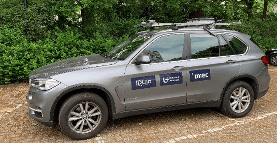
The vehicle that is used is a BMW X5 xDrive25d LO with automatic gearbox from 2014 that is provided by the University of Antwerp. The vehicle is equipped with an Onboard Unit (OBU), power system and communication hardware as discussed in the next section. This vehicle can be driven and used as a mobile node in a V2X context.
This vehicle has an OBU installed, divided into two parts, the OBU on the roof and inside the vehicle. The figure below depicts the architecture of the OBU which consists of several modules.

On-Board Unit on the roof
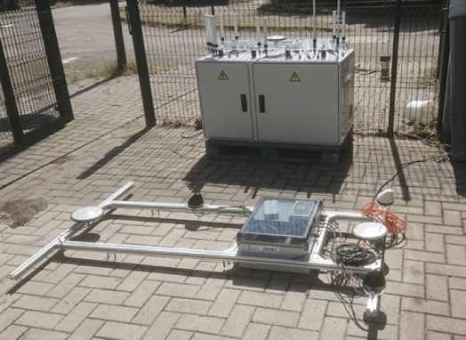
The roof unit contains all the communication hardware, the V2X processing hardware and the sensor processing hardware. The figure below shows the roof unit prototype with all the hardware installed. The centre of the roof unit is the Intel NUC processing unit which has V2X modules and communicates with the processing unit within the vehicle.

The antennas and vehicle sensors (LiDAR, camera, etc.) are mounted on the aluminium frame around the vehicle unit. The following table contains a list of all the hardware of the roof unit and their specifications.
| Specifications OBU Roof Unit | |
|---|---|
| V2X processing unit: NUC7iDNKE | I7-8650U Processor 8GB system memory 120GB SSD |
| Phoenix gigabit switch | 8x 1Gbit/s ports |
| ITS-G5: Cohda Wireless OBU | Cohda MK5 OBU Mobilemark MGW-303 antenna two 5.9GHz antennas for DSCR with an active GNSS antenna |
| C-V2X: Cohda MK6c EVK | C-V2X PC5 (Qualcomm 9150) Bandwidth 10 MHz 2 C-V2X antennas 1 GNSS antenna Security; SXF1800 FIPS 140-2 level 3 compliant |
| 4G module: Mikrotik wAP LTE kit | LTE Category 4 (150Mbps downlink, 50Mbps uplink) Internal antennas with support for optional TS9 external antennas |
| GPS module: AsteRx-m2a | RTK receiver PolaNt-x MF antenna |
| Lidar sensor: Velodyne VLP-16 | 100m range 16 channels Rotation rate between 5Hz – 20Hz Field of view: +15.0° to -15.0° (vertical) Field of view: 360° (horizontal) |
On-Board Unit inside the vehicle
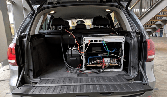
The vehicle unit contains the main processing unit of the OBU and an independent power system that powers the entire OBU (vehicle unit and roof unit). The main processing unit is an Nvidia AGX Xavier device which has an ARM processor in combination with a dedicated Nvidia GPU. The power system is a custom unit that has the capabilities to power the OBU for several hours (+5 hours in the current configuration) without using any power from the vehicle. This makes the vehicle unit, alongside the roof unit, moveable between cars because the OBU is not connected to the vehicle’s power system.
| Specifications OBU Vehicle Unit | |
|---|---|
| OBU processing unit: Nvidia AGX Xavier | 8-core ARM v8.2 64-bit CPU 512-core Volta GPU 16GB 256-Bit LPDDR4x 32GB eMMC storage |
| CAN sensor box: Raspberry Pi 3 B+ with can shield | Quad Core 1.2GHz Broadcom BCM2837 64bit CPU 1GB RAM 100 Base Ethernet PiCAN 2 can interface |
| Mikrotik CSS326-24G-2S+RM network switch | 24x 1Gbit/s ports 2x SPF+ |
| Power system | Input: 12VDC battery Output: 5VDC, 12VDC, 230VAC Capacity: 1000Ah at 12V |
1.2 Road Side Unit
The Road Side Units (RSUs) are deployed along the E313 highway in Antwerp on top of the gantries. Seven RSUs have already been deployed at E313. The antennas of the communication modules are mounted on top of the RSU and the RSUs at the site are all installed in the top of the gantry that spans the highway.
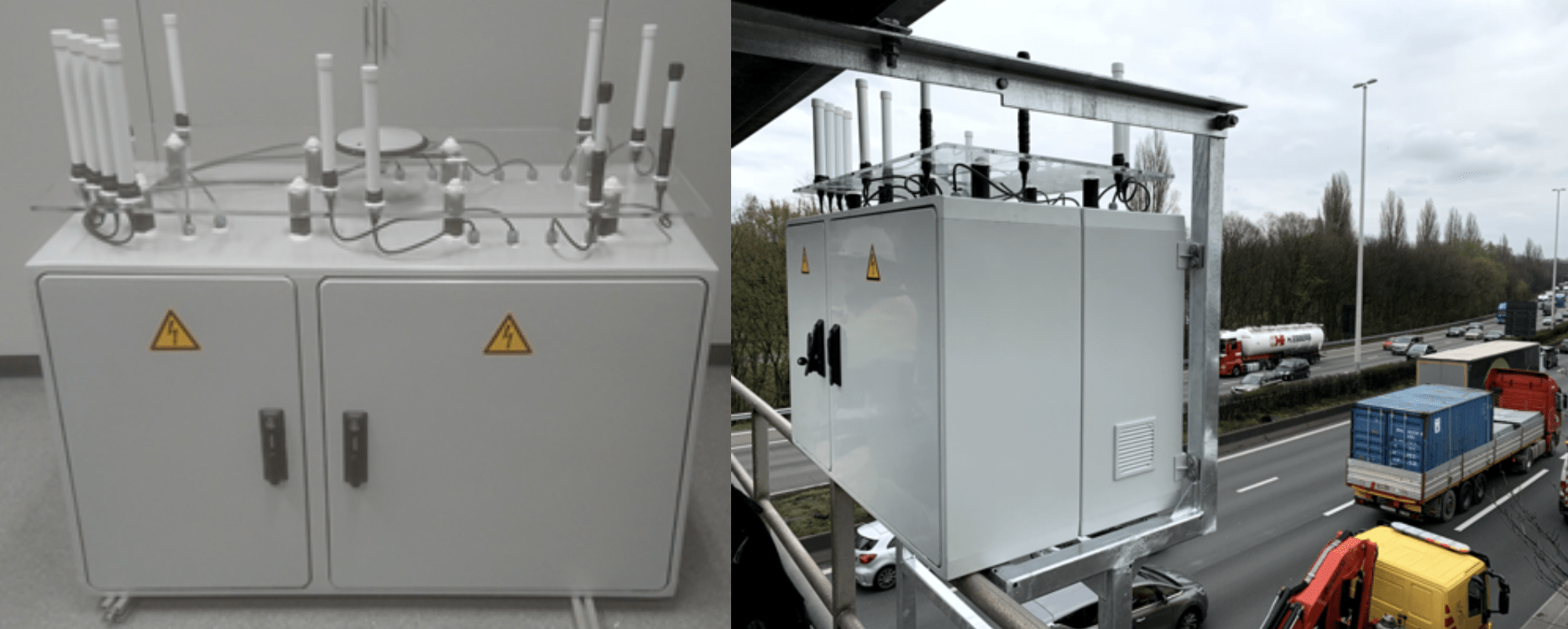
Each RSU consists of a large electrical cabinet which houses all the different modules of the RSU. These include modules for wireless communication, modules for local processing on the RSU and modules that allow the RSU to be managed and, if need be, recovered remotely.
This RSU contains hardware and communication modules to provide V2X communication experience.

| Specifications Road Side Unit | |
|---|---|
| GPCU | Supermicro CSE-512F-350B; 19’’, rack-mountable IPMI-module, 2x 1GigE, 2x USB3, 2x USB2, 1x VGA Intel Xeon Broadwell E5-2620V4 @2.1GHz (8 Cores) 32GB DDR4-2666 2Rx4 LP ECC 1TB Samsung 860 EVO SSD Supermicro AOC-STGN-i2S PCIe Renkforce 7 + 2 port USB 3.0 Navilock NL-8012U |
| SDR: Ettus USRP N310 | 10MHz -> 6GHz frequency range 4 RF Channels with separate TX and RX connector per channel Upto 153.6 MS/s (mega-samples/second) 2x 10GigE SFP+ ports for high-bandwidth data transmission 1x 1GigE Management Ethernet port Internal 50ns-accurate GNSS receiver PPS-input port (to allow for synchronization against an external clock source) |
| GNSS Septentrio AsteRx-m2 OEM Base | Simultaneous tracking of all supported GNSS signals GPS, GLONASS, Galileo, BeiDou, SBAS, QZSS, … Accurate to within 5 nanoseconds 1GigE network interface Provides time synchronization via Ethernet, USB, PPS output signal (connected to SDR) |
| V2X Modules | ITS-G5: Cohda Wireless MK05 RSU LTE-V: Cohda Wireless MK6c EVK 2x antenna connector (connected to 5.9GHz antennas) Internal GNSS receiver (connected to a GNSS antenna mounted inside the RSU) 1x 1GigE Ethernet port for data communication and management of the device |
| Managed Switch Planet IGS-5225-16T4S | 16x 1GigE RJ45 port 4x 1GigE SFP port Management options: Web GUI, SSH & Serial Console, SNMP Full 802.1Q (VLAN) support including VLAN-in-VLAN functionality Link aggregation, QoS, Bandwidth control 19″ Rack mountable, 1U |
| Managed PDU Racktivity PM0816-01 | 1x C20 16A Power input port 8x C14 10A Power output port 1x 1GigE Ethernet port Management options: Web GUI, SNMP Built-in monitoring: environment temperature, power consumption Configurable per-port over-current protection 19″ Rack mountable, 1U |
| LTE Modem | Mikrotik wAP LTE kit |
| VPN Endpoint / Recovery System (APU) PCEngines APU2C4 | CPU: AMD GX-412TC, Quad Core @1GHz RAM: 4GB DDR3-1333MHz Storage: 60GB SSD Connections: 3x 1GigE Ethernet port, 2x Serial port, 2x USB 3.0 port Recovery features: Hardware watchdog, iPXE pre-boot environment, can boot into recovery-OS over the internet |
| Enclosures | ABB PolySafe PS352 IP protection rating: IP54 |
| Antennas | “5.9GHz” SmartEQ 710274: 2.4-2.485 GHz (5.6 dBi), 4.9-5.9 GHz (6 dBi) “3.5GHz” MobileMark ECO63500-WHT: 3.4-3.7GHz (6 dBi) “Quad Band” SmartEQ 710725: 790-960 MHz (2.7 dBi), 1710-2170MHz (5 dBi), 2170-2690MHz (7 dBi) GNSS Septentrio PolaNt-x MF: 1160-1252MHz (3 dBi + 39 dBm amplifier), 1525-1610MHz (3 dBi + 39 dBm amplifier) |
1.3 Experimentation
Experimenters using the testbed get physical access to the vehicle and its OBU and can drive towards the location of the RSU. Moreover, the access to these OBU and RSU can be prepared remotely for preparation purposes.
1.4 Deployment
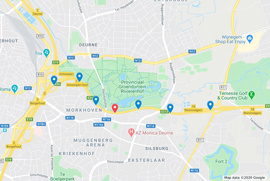
As shown on the map below, the 7 RSUs are located in the E313 Highway directing towards Herentals from the Ring of Antwerp. The node in red can be tested from inside the highway or in a residential street. The blue nodes are to be tested by driving inside the highway following the track towards Wommelgem.
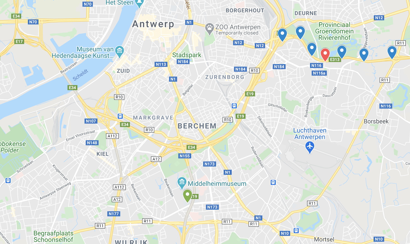
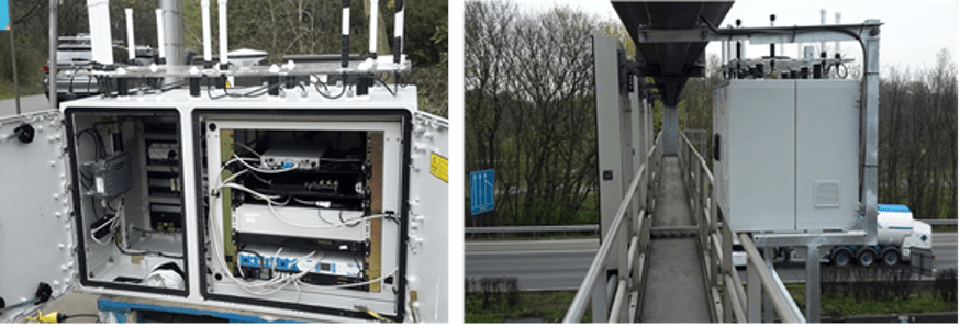
In addition, for the preparation of the test or a static scenario, we also have an RSU and an OBU at a permanent site (green dot in the map above). There, the experimenter can test V2X communications functionalities before going to the field tests. Since in the permanent site, the OBU that act as car node is installed in a fixed environment, this allows the testing of V2X communications without mobility features, or having nodes going mobile. This hardware is installed in the Groenenborger campus of University of Antwerp and can be accessed remotely. This means that we have two sites for the V2X testbed, one in a real highway setting, one in a laboratory environment.
Contact
Bart Braem: bart.braem@imec.be
